
ENGR 14, Introduction to Solid Mechanics • Fall 2022
YOSEMITE BRIDGE MODELDesign and analysis for a bridge model intended to span a river in Yosemite National Park. Made of balsa wood. SkyCiv used to supplement member analysis calculations on the truss in order to best support a load of 150 - 250 N. Pictures and after-testing report included below.
DESIGN REQUIREMENTSBridge must span a length between 24 cm and 25 cm.
Must have minimum height of 3.5 cm and a width between 3.5 cm and 4.5 cm.
Must have a maximum mass of 20g.
Target support load must be between 150 - 250N.
Must be constructed with balsa wood, wood glue, and paper punches.
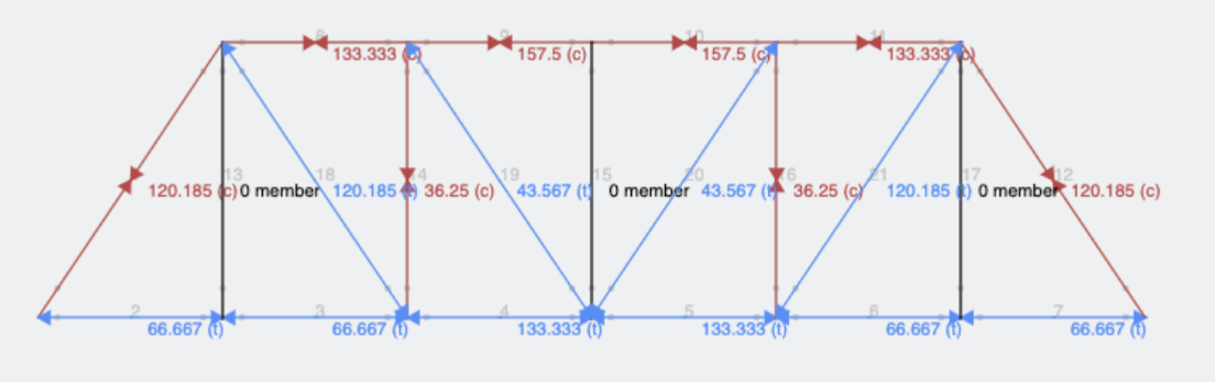
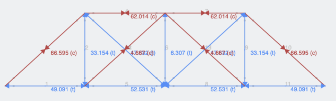
Design 1: Pratt Truss with 4 cm members
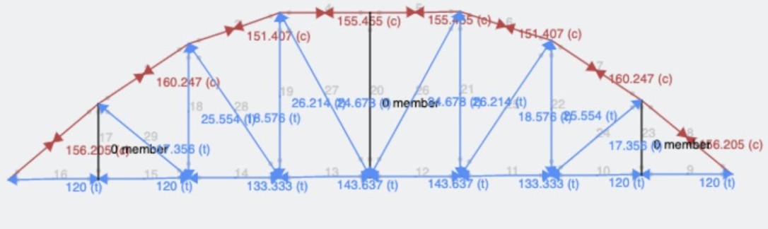
Design 2: Parker Truss
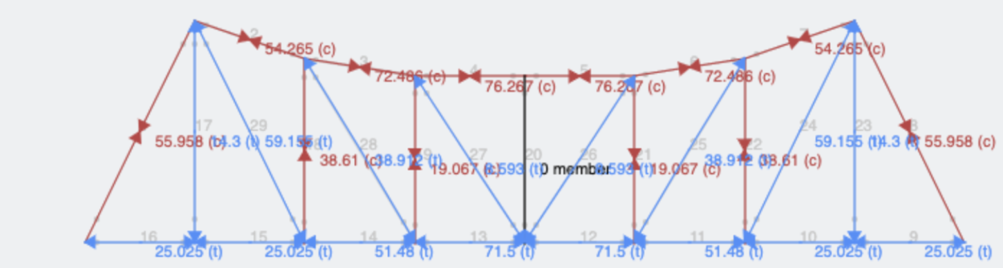
Design 4: Inverted Parker Truss
Design 3: Pratt Truss with 6 cm members
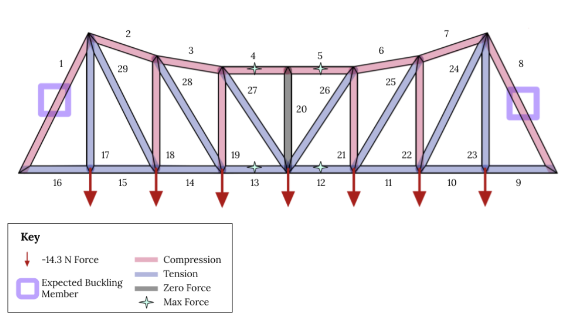
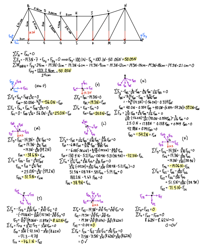
Diagram (above) with supporting calculations (right) of Design 4 (the inverted version of the Parker Truss.
We compared complexity, number of members and joints, novelty, and functionality. Several Pratt Trusses were examined with varying heights, number of members, and crossing members. We also looked at a Parker Truss to experiment with more complex shapes. After tweaking our models in SkyCiv, we found the best way to accomplish the force buckling goal was to create a longer member. Our team ended up selecting a completely novel design inspired loosely by the beautiful bridges in the Bay Area.
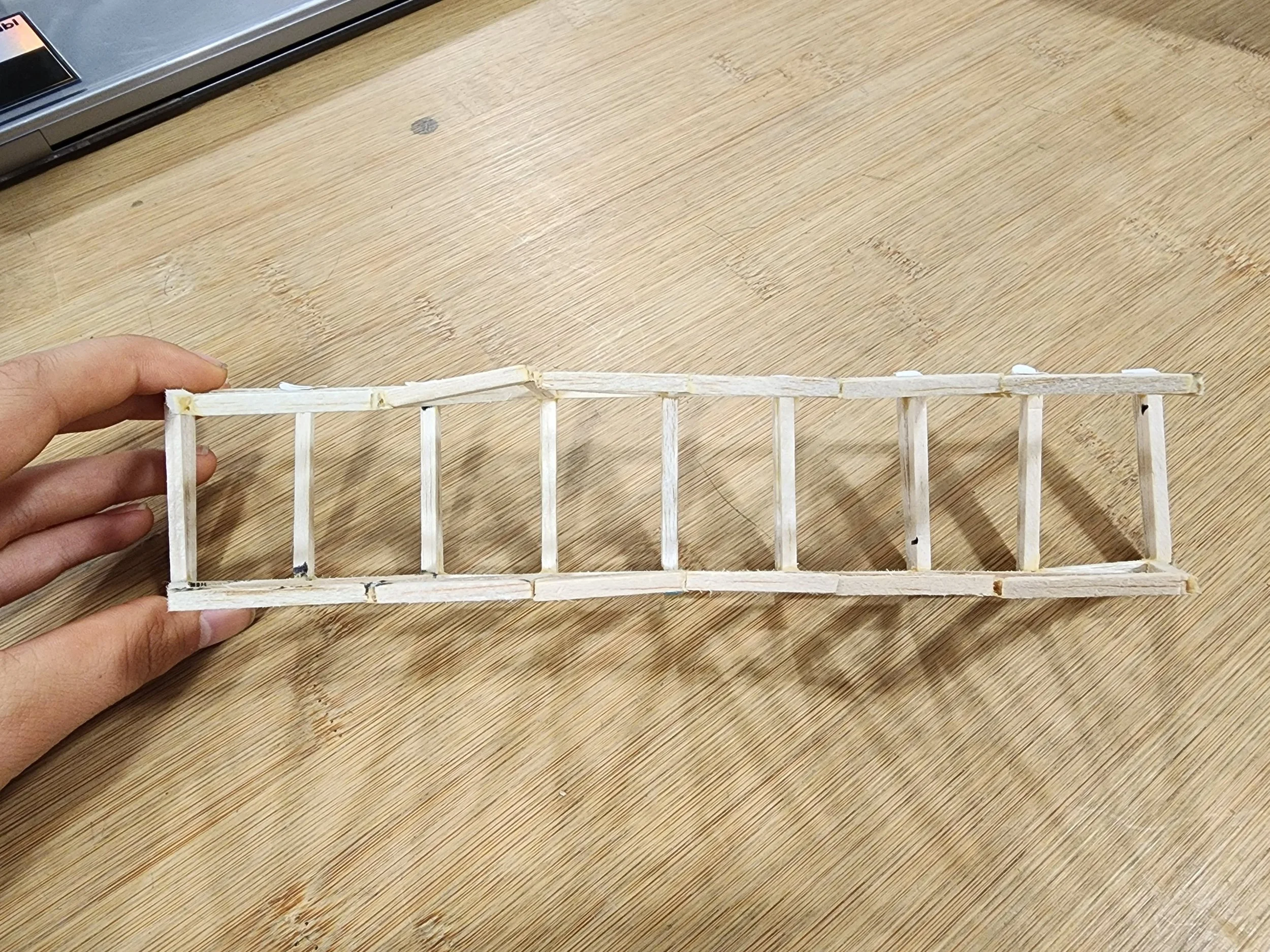

Building process (pin and then glue)
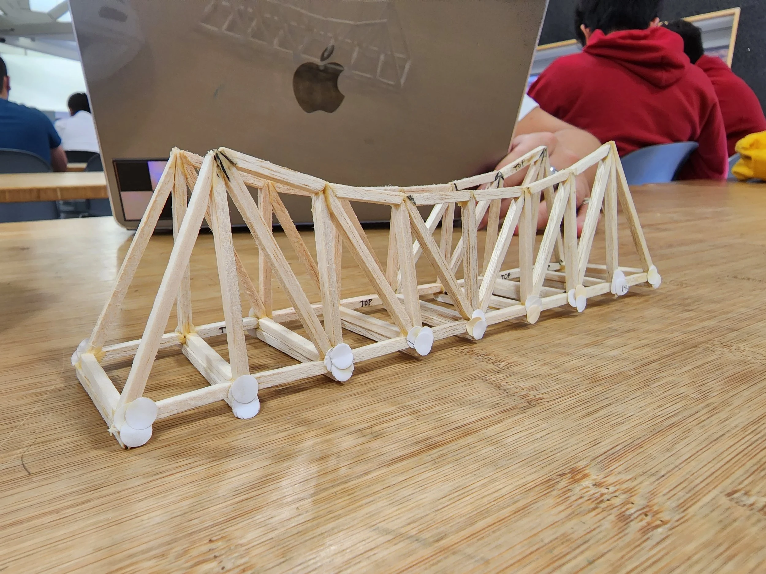
Finalized Bridge
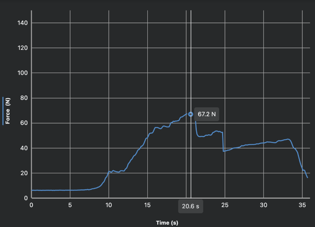
Bridge after testing
We believe that this was a buckling failure. The members did not experience breakage and the final load was below our target. One suggestion would be to include cross members. We unfortunately forgot to include these at the top of the truss. As shown in Figure 9, the members at the top of the truss were not straight after the bridge failure. Perhaps including these cross members would have minimized some of the buckling at the joints by providing more support.
Another possibility would be to improve joint construction. We ran out of paper hole punches to use to support the joints and only managed to support the joints on the bottom of the truss. Because our design was quite complex, there were lots of members and our joints were complicated. Several of the members needed to be sanded down to very odd angles, and it is possible that we could be more precise with these angles in the future. In addition, our bridge did not lay perfectly flat on the testing surface, which may have contributed to unanticipated forces.